Write Out the Meaning of the Feature Control Frame as a Sentence
Today our featured GD&T term is "feature control frames." We at Metalcraft decided some time ago to put together a glossary of sorts. It will be alphabetized in proper fashion but as various terms are added they will not be added in A to Z fashion, but more in order of importance, or more importantly, how we feel that day.
Approaching GD&T As An Outsider
As we've explained before learning GD&T is like learning a new language. First of all it is composed of an array of symbolic characters that make up a system of mechanical drawing engineering controls. The system serves our world to make the task of engineering definition more precise, more specific and as abbreviated as possible without suffering loss of detail.

I begin today's term with this synopsis of our wider subject because feature control frames play a specific role in the administering of our symbolic controls, not the only role, but probably the most important one. Take a moment to think about our world as the conglomeration of all the physical amenities and goodies we dote on and ride around in and pay a great deal of our attention and money to. We have automobiles, airplanes, computers, cell phones, appliances, implements of social enforcement and the list goes on. These things are the focus of our human energy and they all require engineering. They require more than engineering but our focus, here and throughout our sphere of influence, is making these things come to fruition and at the very heart of this effort, we believe is the proper use of advancement of GD&T. 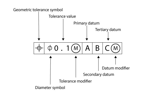
What Are Feature Control Frames?
And so we are here to define the feature control frame . The feature control frame (FCF,) is what I like to call the engineer's statement. It is a method that arranges a number of our GD&T symbols to say something. Actually a properly formatted feature control frame makes a demand; it states an instruction about a feature or feature's relationship as a constituent of a part. Here is an example of a simple feature control frame. 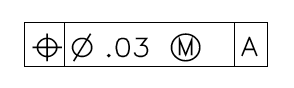 The way we should read this symbology is like this:
 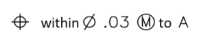 Or in words the engineer is stating to " hold position within a cylinder shaped tolerance zone to .03 inches at maximum material condition relative to datum A."
How Do Feature Control Frames Work?
This frame has three compartments. The first is the characteristic control compartment. It communicates the type of geometric control the engineer wants to apply to the feature or features. The second compartment is the tolerance compartment. Along with the value of the tolerance the engineer is applying to the control it can and often does have a number of symbols in it. The reason for that is because controls are often more complex than just stating that there is a tolerance to be held, like + or – some value. In GD&T tolerances are 3 dimensional. Some people may disagree with that because there are a number of characteristic tolerances that have both 2D and 3D versions of a control, like the profile tolerance. There are 2 versions of that characteristic tolerance; there's profile of a line and profile of a surface. Profile of a line is considered a 2D control but it actually controls each line item of a subject surface, so the way I look at it, its effect on a surface is 3 dimensional. It affects control on the whole surface.
Tolerance and Feature Control Frames
So now back to the tolerance compartment of our feature control frame. The frame above first has a diameter symbol in it. That is known as the tolerance zone descriptor. In this case it states that the zone for the position control will be a cylinder. Next there is a value for the tolerance zone. In this case it's .03, which means the cylinder, within which the axis of the feature being controlled will be contained, will be no more than .03 units of measure or in this case inches.

Condition Modifiers (Maximum Material Condition)
The last thing in the tolerance compartment may be (not all FCFs have one,) a condition modifier. In this case the feature condition modifier is maximum material condition (MMC.) This modifier adds a layer of complexity to our statement. The engineering behind this position control allows tolerance on both the controlled items in our FCF but also the items in the parts or assemblies that will become assembled to this item.
Flexibility Matters
Flexibility is a necessity in manufacturing so as complex assemblies make adjustments to suit the people, tools and conditions of their maker's the suitable circumstances for how these parts and mechanisms fit together allow choices in the processes. If a part with three fastening bolts has to assemble with a bracket that has three corresponding holes for the bolts, the largest allowable holes in the bracket naturally allow a greater range of position control for the placement of the holes that will still allow the bolts to pass through them when the two parts get assembled. So when the bracket is manufactured with the 3 holes in it and those holes are chosen to be bigger than smaller, the position of their placement becomes easier and hence less expensive to make because it is true that tighter controls usually cost more money.
Tolerance and Feature Control Frames Continued
Take a deep breath as we head back to the feature control frame and our tolerance compartment. It has a zone descriptor, a tolerance value and a feature condition modifier. The modifier area of the compartment can have more complex condition modifiers with modifier zone values, modifier zone placement symbols and values and more. But that is for another time. If there is no material condition modifier the rule is that RFS is the default condition. Regardless of feature size means that the stated tolerance is to be held no matter what the controlled features measure.
The Datum Compartment and Feature Control Frames
The last compartment in our FCF is the datum compartment. Sometimes there is no datum compartment and sometimes there are a number of them. Theoretically there can be any number, depending on what the engineer needs. I've seen parts with dozens of datums so it depends on the circumstances. Another thing that might be found in the datum compartments is a condition modifier for a datum, also known as datum mobility. It shows up with the datum symbol as m , which in this case is not a maximum material condition modifier but a maximum material boundary modifier. When a symbol like this accompanies a datum that datum must be a feature of size and when used to advantage this modifier allows "datum shift" when calculating all the factors that make up the position mathematics. The datum feature of size is treated much like a feature at MMC; as it departs from MMB the actual datum feature can be arranged or shifted within the bounds of its size to see if a feature position can squeak into tolerance when this is used. In our GD&T language of symbols feature control frames are the engineer's statement of tolerance.
Write Out the Meaning of the Feature Control Frame as a Sentence
Source: https://metalcraftind.com/definition-terms-feature-control-frames/
0 Response to "Write Out the Meaning of the Feature Control Frame as a Sentence"
Post a Comment